CAD Craft
A resource to CAD Craft specialists, and a showcase of my work — in both material and virtual worldsArchive for SolidWorks
Part 2: Configurations & Modular Design
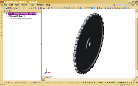
Following on our discussion in Part 1, I used a Gear Assembly to show the creation of size configurations for the Gear. In Fig. 1 below, you can see in the Configurations Tab that there are currently two configurations: the Default, and Medium. (I’m using screen shots because some of the feedback I received expressed concerns that the video went too quickly.)
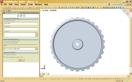
In Fig. 2, I am creating a third configuration, Large. Note at the bottom there are two check boxes, the first of which Suppress Features, is very important. It provides a setting so that any features I create for this configuration are automatically suppressed in the other configurations, instead of me having to do it manually. You can also designate acolor for each configuration, which makes it simpler to recognize different configurations at the assembly level, which is particularly handy when the difference(s) between configurations is not immediately obvious. This applies at the part & assembly or subassembly level.
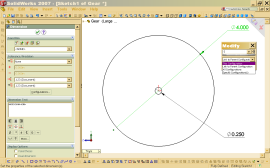
Fig. 3, the sketch for the primary extrusion of the wheel disk is open, showing me modifying the diameter dimension. You will note that on the dimension dialog, there is a tab selected, opening a flyout allowing me to specify which configuration this diameter is to apply to.
REVISED–Part 1: Configurations & Modular Design
I went back and reviewed where I was going with this post, and more critically, what was needed to effectively get across the comprehensive grasp of these principles, and I came to the conclusion that this needs more illustrations, and it needs to be in at least three parts. What follows is Part 1, with some fairly significant revisions…
><><><><><><><><><><><
Principles & Concepts
One of the challenges many CAD newbies complain about is that most high end CAD packages start with the assumption that the newbie is coming from a CAD background of some sort, most likely from a competittor program. With the growing confluence of design tools I have been commenting on here, this is more and more often not the case. That’s why I’m going to start this discussion with the basic concepts and ‘build’ from there.
While there are various tutorials & guides online about configurations, a discussion of the ‘when’ & ‘why’ — even the what — is not often covered. Configurations are one of those features which, if you don’t know about it, you might not even think to wonder about it, especially if you don’t come from an engineering background. However, in many ways, the premise behind configurations is intimately linked to foundation engineering principles, including modularity, or modular design.
Let’s use an example we’re all familiar with — computers. When IBM opened its PC architecture to other vendors, triggering the ‘flood of the clones’, this was a grand lesson in the +’s & -‘s of modular design. The PC is an example of modular design:
- The core of a personal computer is the motherboard, which mounts the CPU, among other things. It is the nexus point coordinating all of the peripherals to function in unison, including
- Video card
- Network card
- Modem card(for some)
- Sound card(most newer computers have integrated this into the mother board), etc.
As the indentation shows, the peripheral cards are subsidiary to the motherboard. Each type of peripheral is a component which fulfills a specific function needed by the systmem, and facilitated by the motherboard. It is worth noting as an aside that this “indentation” is a mode of representation which carries a specific meaning in engineering — it is used in what we call an indentured parts list. It is a valuable documentation tool.
The PC is a good example of modularity because once IBM set the interconnect standards — what sort of edge connectors did each card need to interface with the motherboard — vendors then based their designs around this constraint. Parameters of size, including net component height were also important. What this meant was that it created a broad spectrum of vendors who chose a niche, an area of expertise, which became the basis of a subsidiary industry. There are now multimillion $ corporations who only build one type of peripheral, like ATI or NVIDIA who make video adapter cards. Each card is its own module. Because there are many types of video cards, even from the same manufacturer, each model corresponds to a ‘configuration’ in the context of our discussion. Obviously, you can have configuraitons within configurations, but let’s look at some examples of this.
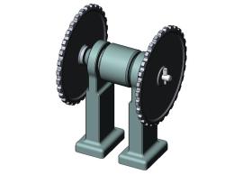
This simple drive assy can have a series of various configurations. For instance, there might be several configurations of the gear wheel alone, based on the number &/or size of teeth, the diameter of the wheel, and combinations of these. Each variation in a parameter of the wheel would constitute a configuration of the wheel AND the assembly. So, for example, a version of the assembly where the two wheels are of different sizes would also constitute a different set of configurations. This might be done to facilitate the use of the assembly in an application where the gear ratio needed to step down or step up in order to effectively engage the systems involved.
Seeing how this could impact this assembly, we can look at how configurations in the model facilitate these variations in the assembly.
In the above video, you can see that I already have created secondary configurations in the Gear Wheel part, the Gear-Shaft assembly, as well as the top assembly, Axial Example. In the video, follow as I switch between configurations in each model, and the resulting effect. This gives some insight into configurations. As stated, part of what this enables is a reduction in the number of models, and a simplification in the feature & assembly trees at the left.
One of the key aspects of this, which I will show in Part 2 later this week, is how you can control configurations as you create the part through the specification of which configuration a given sketch, sketch dimension or feature is intended to apply to. I will also discuss the use of design tables in creating & managing configurations.


